Data Pods
Cooling the Cloud:
Climate-Adaptive Design for the Data Center of the Future

The Emergent Typology of the Data Center
The data center is an emerging building typology, proliferating in the 21st century to provide cloud computing services to a rapidly growing number of users worldwide. Cloud Computing enables efficient hosting of pervasive applications from consumer, scientific, and business domains. Data centers are the physical infrastructure of these Cloud applications. They provide protected environments for the processing needs of users. These centers consume large amounts of energy, partially due to the servers’ electric load. However, more significantly, 40 percent of the energy load is spent by the mechanical systems necessary to reject the heat produced by the servers. In order to minimize data centers’ carbon footprint, large Cloud service providers, like Microsoft, Google and Facebook, have initiated research on sustainable design strategy for data centers.
Philadelphia is long past its hey-day of being one of the epicenters of the industrial revolution in the US. But it’s physical footprint, remains to this day. As an environmental designer the impetus was on focusing on abandoned sites, starting with those consisting of a robust pre-existing structural framework, such as bridges and piers to accommodate the ever-growing demand for data storage in the digital era.
Research
URBAN ANALYSIS PHILADELPHIA
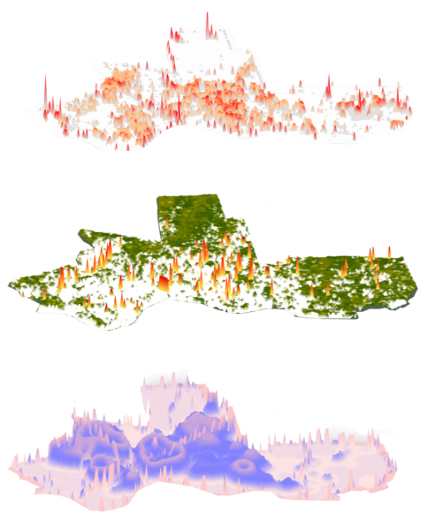
Urban Hot spots
Vegetation and Discomfort Temperatures
Resident Density

POTENTIAL SITES
The site chose to develop was the Graffiti Pier and it is between Fishtown and the gentrifying Port Richmond, and is prime for development. The goal is on doing the least amount of work on the site as possible and really finding the niche where the data centers can co-exist with the pre-existing structure and the people.
Study on the Heat Dynamic Strategies of Data Centers

No Containment Strategy

Cold Aisle Containment
Hot Aisle Containment
ADVANTAGES OF HOT AISLE CONTAINMENT OVER COLD AISLE CONTAINMENT
No additional equipment would be required for the cooling for the UPS
By separating the hot aisle, there is more cold air circulating in the system thus behaving as a redundancy strategy
Wind and Radiation Study

Frequency of Wind and Average Wind Velocities
After mapping the wind direction, ratio and velocity in Philadelphia, a secondary analysis allowed me to eliminate the low wind zones by including limits. The 1st limit depicted by the yellow hatched line represents the wind direction and velocity and the second depicted by the red hatch represents the conditional requirement for wind ratio in a particular direction.

Annual Wind Inference vs. Annual Wind Rose Diagram
Result: Eliminating Low Wind Zones

Form Exploration Process

Design

Module Development

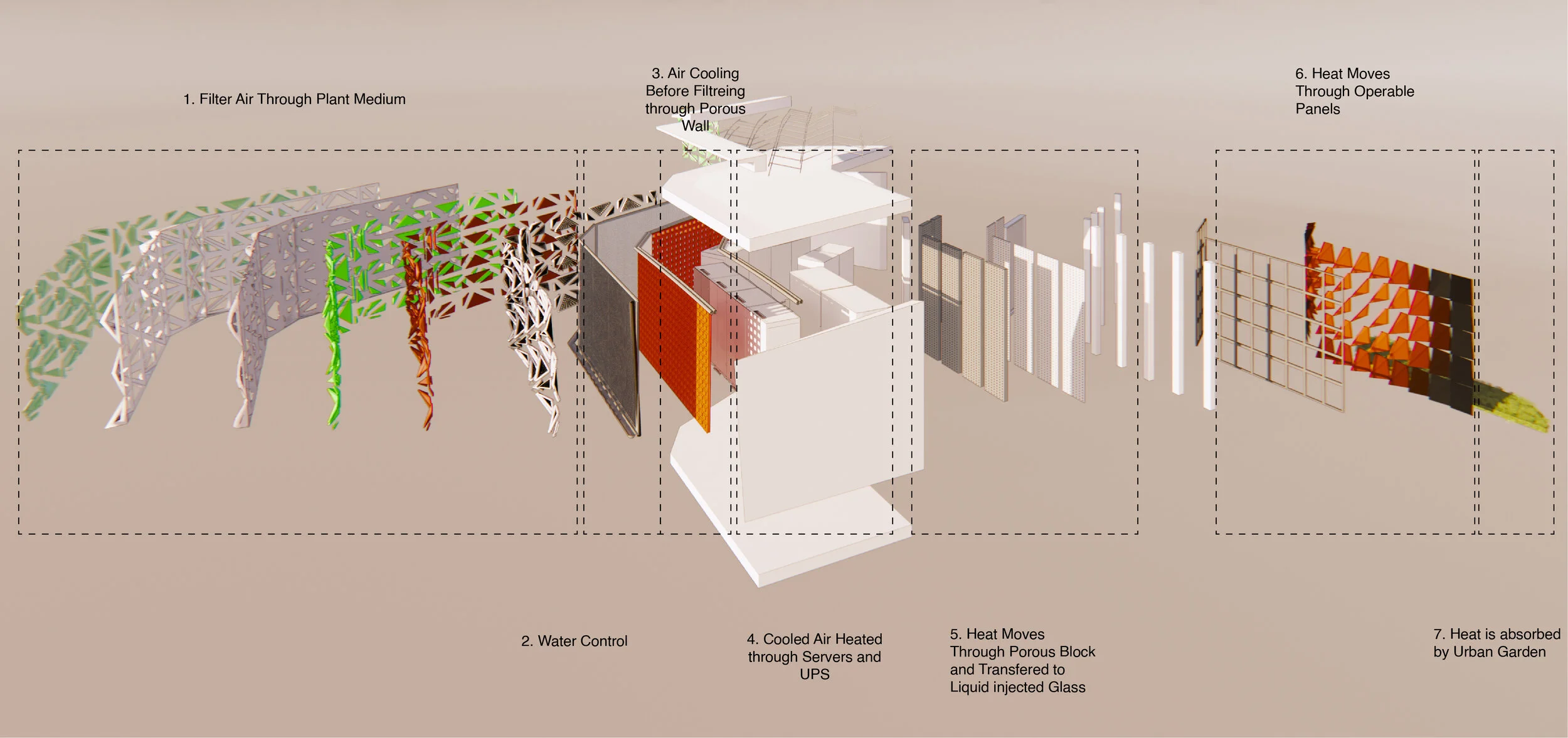
Process Diagram
By cycling the water through the façade the module accomplishes three goals. Firstly, to irrigate the plant-based filter media. Secondly, to cool the air circulated to the server’s insider the module. Finally, to ensure that the cooler air is contained to the lower region, after which it is recirculated at the base of the servers.

Section
Modular Typologies

Semi-Permeable Façade
Air intake across 260°
Module 1

Permeable Façade
Air intake across 180°
Module 2

Module 1

Module 2
Heat Dynamics and Air Flow Analysis
The first pod allows the movement of air inside the module on two side across 260 degrees. In the first module, the air movement is restricted to the lower region of the semi-permeable façade. After which it is allowed to circulate to the lower region of the data module. As the air heats up, it rises and exits the pod through operable panels on the roof through Stack effect.
In the second module, the air movement is restricted to one side across 180 degrees. The entire façade is permeable and through advection the air naturally moves out of the pod horizontally.
Module 1

Exploded Component Diagram

Process Diagram
The envelope consists of three layers. Firstly the air passes through a plant based-façade which filters and dehumidifies the air. The air movement in this second layer, however is contained to the lower region of the module. This secondary layer is the space wherein pipes that carry cool water run above thus creating a pressure difference and temperature difference, cooling the air and containing it below. These pipes course within a gap between the module’s primary plant-based envelope and secondary offset wall. The third layer is the vapor barrier to control the percolation of vapor to the servers.
Module 2
This module finds purpose in those areas where air movement is restricted in one direction. The other end of the module, as it conducts and transfers heat could serve other purposes such as providing heat for an urban garden. Thus establishing a relationship between the ecosystem and the machine.


Exploded Component Diagram
Process Diagram
In the second module, there exist two types of facades. The front façade is similar with the exception that the envelope is completely permeable. The second façade through which the hot air escapes however employs a different strategy. As the air heats up through the module and exits, it passes through four layers. The first is the a vapor barrier, which exists more as a precaution to restrict water vapor from entering the module. The second is a porous clay block. The third is a porous glass block infused with water which behaves as a thermal storage wall and allows it to pass through it to the outside. The fourth layer is the operable panels.
Bio-Filtration System

Bio-Wall Layers
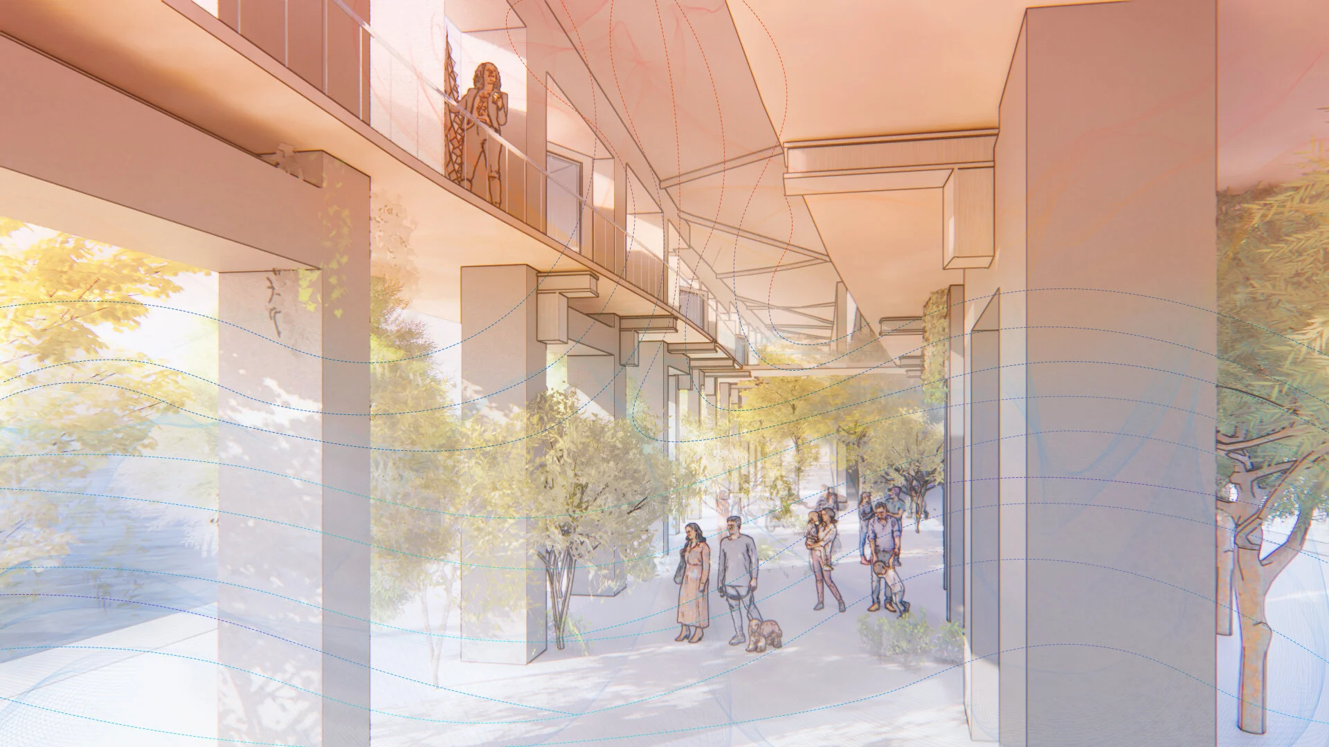
Daylight Study

This is a daylight analysis of the urban space under the pier that could be used as an urban garden.